# Enapter Web GUI
# Getting Started
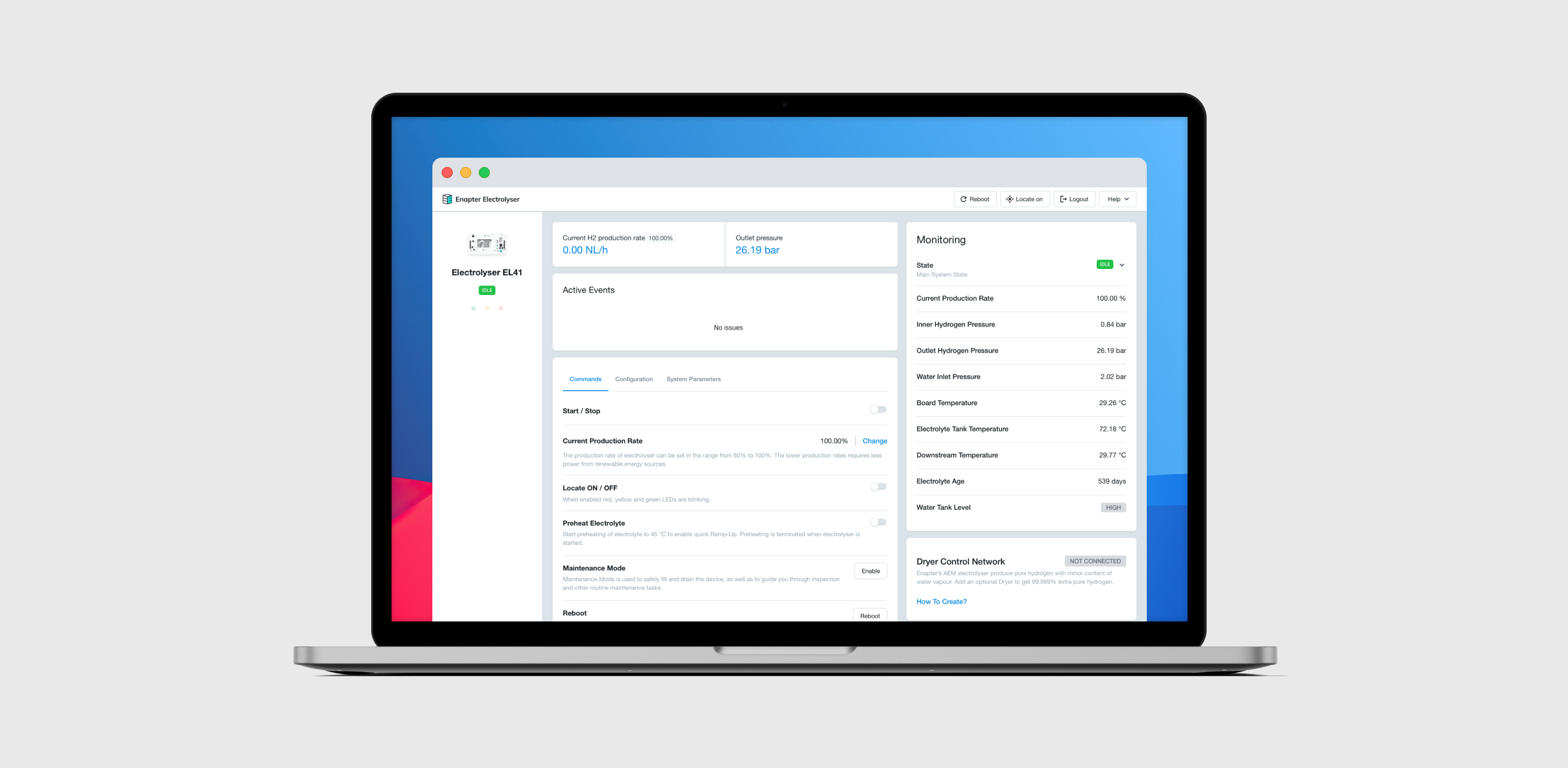
Enapter Electrolyser Web GUI (Graphical User Interface) made for local control and monitoring using a web browser.
Note
Supported versions of Electrolysers:
- EL 4.1 with firmware version 3.4.0 or later.
- EL 4.0 with firmware version 3.1.0 or later.
- EL 2.1 with firmware version 1.6.0 or later.
Warning
Electrolyser Web GUI works over an insecure HTTP connection and was designed for usage in isolated Local Area Networks for Operation, Administration and Management. Please take into account that connection to public networks such as the Internet is not recommended for security reasons.
Check out video describing main functionality of the Web GUI.
# Connections
Warning
If connected device do not have Auto MDI-X (auto crossover) use an Ethernet crossover cable to connect it to Electrolyser EL 4.0 or EL 4.1.
Connect Electrolyser using one of the methods listed below.
# Single Electrolyser Connection
Note
The DHCP server must be configured and enabled on the PC connected to Electrolyser.
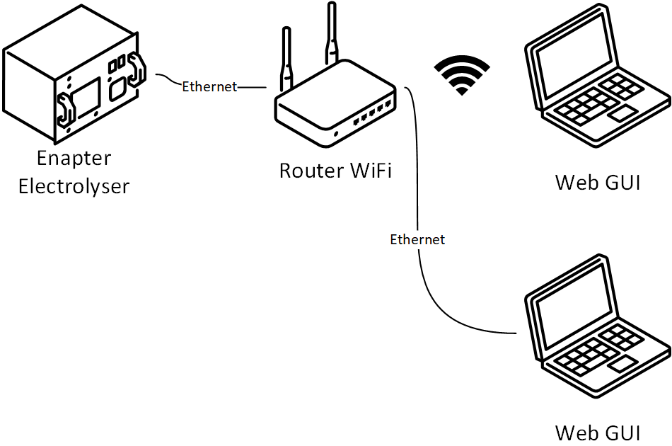
# Single Electrolyser Connection With Router
Note
The DHCP mode must be configured and enabled on the router connected to Electrolyser.
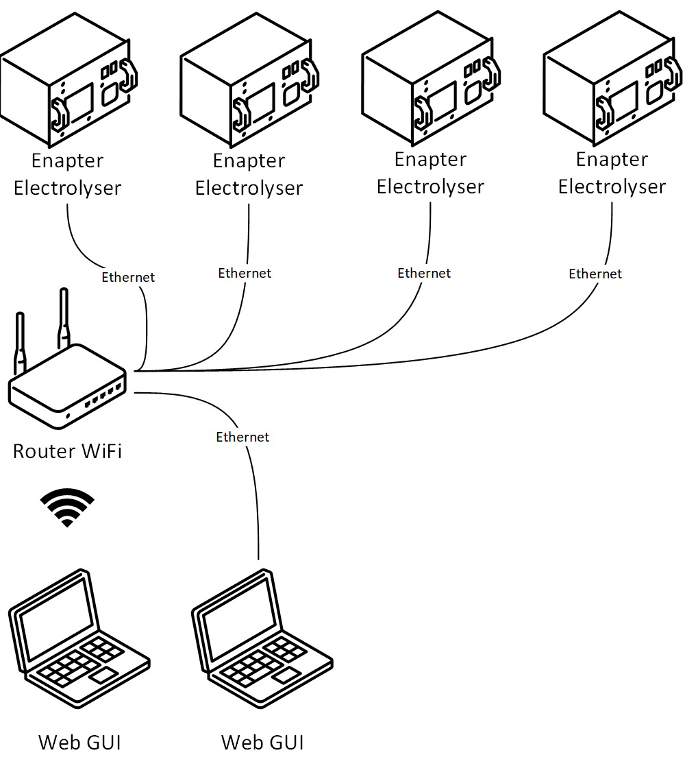
# Multiple Electrolysers Connection
Note
The DHCP mode must be configured and enabled on the router connected to Electrolysers.
# Physical Connection Specification
| Parameter | Description |
|---|---|
| Cable | CAT5 or CAT6 Ethernet cable with RJ45 connectors. Max Distance: 100 meters / 328 ft. |
| Speed | 10/100BASE-T. An Ethernet network transmitting at 10 and 100 Mbps. |
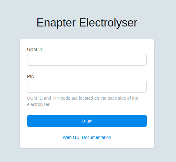
# Access The Web GUI
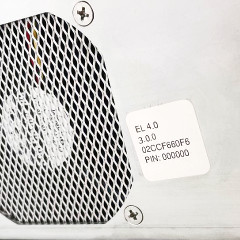
- Find the label with
UCM IDand PIN code on the back panel of Electrolyser.
- Open the Web browser.
- It is two main ways to access the Web GUI.
- Way 1. Use the
UCM IDto create a link with.localhostname likehttp://UCM_ID.local.
For example:http://02CCF660F6.local.
Note
mDNS must be enabled to resolve .local hostname.
Use HTTP protocol.
Warning
It is known issue of using Wi-Fi under Windows with access (name resolution) to the .local hostname. In case you can not access the Web GUI this way please use a local ethernet connection to Electrolyser or IP address as a hostname.
- Way 2. Use the IP address of Electrolyser.
- In opened page enter
UCM IDand PIN code.
- Click on the
Loginbutton to access the Web GUI.
# Layouts
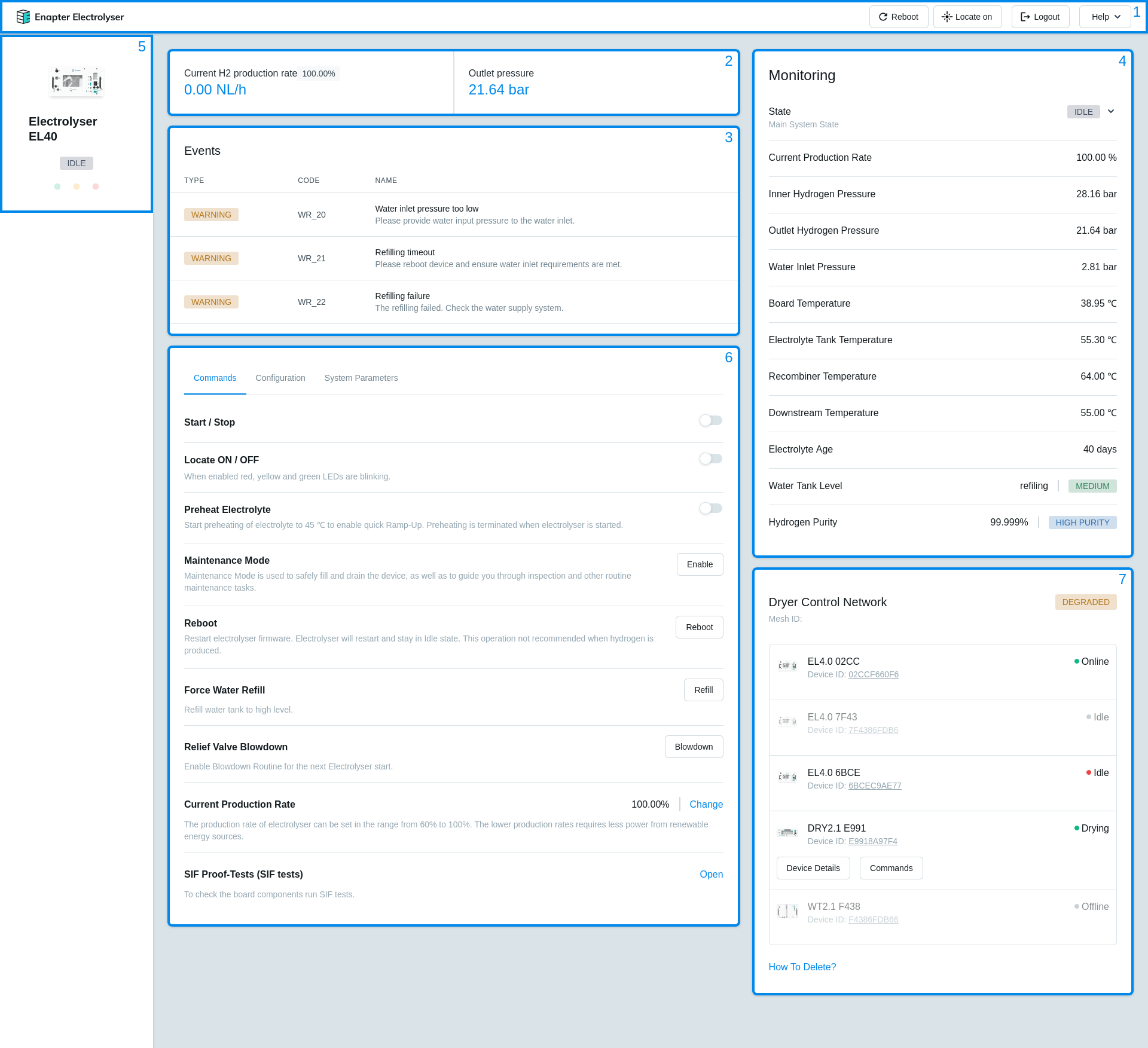
Enapter Electrolyser Web GUI has 7 main layouts:
- The Header Toolbar
- Production Bar
- Events Bar
- Monitoring Sidebar
- Status Sidebar
- Main Configuration Bar
- Dryer Control Network
# The Header Toolbar
| Parameter | Description |
|---|---|
| Reboot | Command to Reboot the device. |
| Locate | Command to enable or disable the Locate device functionality.When enabled red, yellow and green LEDs are blinking. |
| Logout | Command to Logout from Web GUI. |
| Help | Useful links: 1. Our customer service at support@enapter.com. 2. EL 2.1 Documentation. 3. EL 4.0 Documentation. 4. EL 4.1 Documentation. 5. Web GUI Documentation. 6. Modbus Registers. 7. Download Diagnostic (opens new window) - JSON format diagnostic file with statistic and configuration parameters. |
# Production Bar
| Parameter | Description |
|---|---|
| Current H2 Production Rate | Current hydrogen production rate corresponding to the percentage value. In NLh. Current production rate can be set in Commands tab in Main Configuration Bar. |
| Outlet Pressure | Outlet hydrogen pressure. In bar. |
# Events Bar
| Parameter | Description |
|---|---|
| Type | Type of event. Possible types of events: 1. Warning - Heads-up event which should be taken into account to avoid Error or Fatal Error.2. Error - System Stopped. Recoverable error.3. Fatal Error - System stopped. Unrecoverable error. Hardware repair required. Please contact Enapter support. |
| Code | The code of all events for EL 2.1 can be found at Warnings, Error and Fatal Error Codes (opens new window). The code of all events for EL 4.0 can be found at Warnings, Error and Fatal Error Codes (opens new window). The code of all events for EL 4.1 can be found at Warnings, Error and Fatal Error Codes (opens new window). |
| Name | The name and description of all events for EL 2.1 can be found at Warnings, Error and Fatal Error Codes (opens new window). The name and description of all events for EL 4.0 can be found at Warnings, Error and Fatal Error Codes (opens new window). The code of all events for EL 4.1 can be found at Warnings, Error and Fatal Error Codes (opens new window). |
# Events History EL 4 3.5.0
New tab to show Events History.
Every event has the following fields:
TYPE- Onlyerrororcleartypes of events available in the history.EVENT- Name of the event.CODE- Event code.RUNTIME- Moment of runtime when event has occurred.
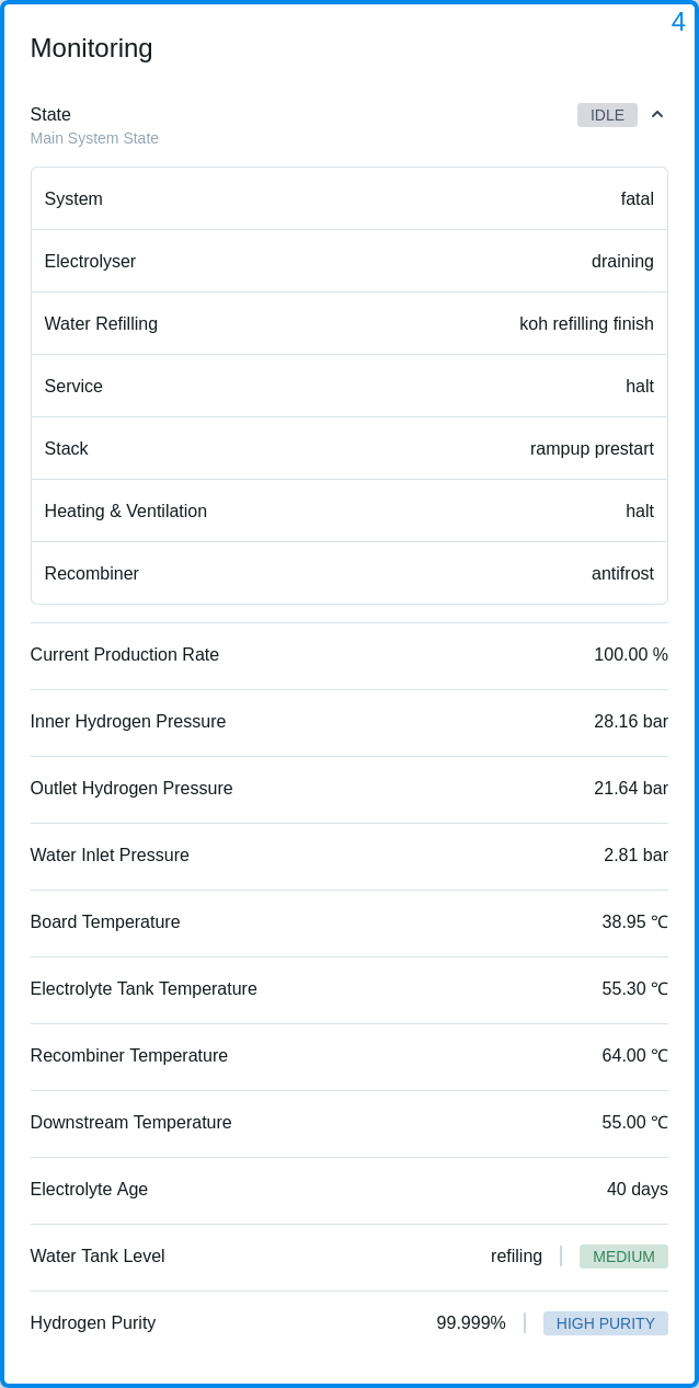
# Monitoring Sidebar
| Parameter | Description |
|---|---|
| State | The main system state of Electrolyser. Possible states: 1. None - System is not started, something goes really wrong.2. Maintenance - Electrolyser is in Maintenance Mode.3. Expert - Special mode for system configuring.4. Error - Electrolyser has Error. Recoverable event.5. Fatal - Electrolyser has Fatal Error. Unrecoverable event. Please contact Enapter Support.6. IDLE - System is ready for start working.7. Steady - Electrolysis process in progress.8. Stand by - System temporary stop H2-produce, because max pressure reached.9. Blowdown - Service process for blowdown valves.10. Curve - Service process to check the stack. |
| System State | Possible System states: 1. None - System is not started, something goes really wrong.2. Operation - System is operation3. Error - Electrolyser has Error. Recoverable event.4. Fatal - Electrolyser has Fatal Error. Unrecoverable event. Please contact Enapter Support.5. Expert - Special mode for system configuring. |
| Electrolyser State | Possible Electrolyser substate: 1. None - System is not started, something goes really wrong.2. Maintenance - Electrolyser is in Maintenance Mode.3. IDLE - System is ready for start working.4. Steady - Electrolysis process in progress.5. Standby - System temporary stop H2-produce, because max pressure reached.6. Curve - Service process for checking stack.7. Blowdown - Service process for blowdown valves.8. Halt - System inactivity. |
| Water Refilling State | Possible Refilling states: 1. None - System is not started, something goes really wrong.2. Second drainning - Second draining.3. IDLE - System is ready for start working.4. Refilling - Filling the water tank.5. Draining - Draining the water tank6. Maintenance - Electrolyser is in Maintenance Mode.7. KOH Refilling - Electrolyte refilling started.8. KOH Refilling Finished - Electrolyte refilling finished.9. Maintenance Refilling - Filling up in Maintenance Mode.10. Try to refill after H2 production - Electrolyser is trying to refill after H2 production.11. Forced Refilling - Water fulfill by user's command.12. Halt - System inactivity.13. Wait Flushing - Electrolyser waiting for command to flush.14. Flushing - Flushing in progress.15. Service refilling - Electrolyser refills water for High Level. |
| Service State | Possible Service states: 1. None - System is not started, something goes really wrong.2. Maintenance - Electrolyser is in Maintenance Mode.3. IDLE - System is ready for start working.4. Blowdown - Service process for blowdown valves.5. Blowdown Stop - Service process for blowdown valves.6. Blowdown Restack - Service process for blowdown valves. |
| Heartbeat State | Possible Heartbeat states: 1. IDLE - System is ready for start working.2. Maintenance - Electrolyser is in Maintenance Mode. |
| HVAC State | Possible Heating, ventilation, and air conditioning (HVAC) states: 1. None - System is not started, something goes really wrong.2. Halt - System inactivity.3. IDLE - System is ready for start working.4. Maintenance - Electrolyser is in Maintenance Mode.5. Preheat - Preheating is activated.6. Management - HVAC in management mode.7. Antifrost - Antifrost Routine activated. |
| Stack State | Possible Stack states: 1. None - System is not started, something goes really wrong.2. Maintenance - Electrolyser is in Maintenance Mode.3. IDLE - System is ready for start working.4. Warming Up - Water heating in the water tank.5. Keeping warm - Keeps heating water and waits to start hydrogen production.6. Hydration - Preparation of the stack for work.7. Rampup prestart - Warming up stack and increasing voltage.8. Rampup pressurizing - Passing purge and wait for 8 bar pressure for leak check.9. Waiting for power cutoff - Waiting for power cutoff.10. Rampup leak check - Checking leak during start.11. Ramp Up 1 - Preparation of the stack for work.12. Ramp Up 2 - Preparation of the stack for work.13. Steady - Electrolysis process in progress.14. Purge - Purge from accumulated moisture.15. Ramp Down 1 - Preparation of the stack to turn off.16. Ramp Down 2 - Preparation of the stack to turn off.17. Max Pressure - Electrolyser stops hydrogen production (Stand by).18. PSU disable - PSU disabled for Curve.19. Halt - System inactivity. |
| Polarization Curve State | Possible Polarization Curve states: 1. None - System is not started, something goes really wrong.2. IDLE - System is ready for start working.3. Starting - Curve state.4. Timeout - Curve state.5. Ramp down - Curve state.6. Purge- Purge from accumulated moisture.7. Data - Curve state.8. Ready - Curve state.9. External - Curve state.10. Halt - System inactivity.11. Maintenance - Electrolyser is in Maintenance Mode. |
| Recombiner State | Possible Recombiner states: 1. None - System is not started, something goes really wrong.2. IDLE - System is ready for start working.3. Halt - System inactivity.4. Preheat - Recombiner preheat in progress.5. Warming Up - Recombiner warming up in progress.6. Ready - Recombiner has warmed up to operating temperature and ready to switch to Steady.7. Steady - Recombiner maintaining the optimum temperature.8. Maintenance - Electrolyser is in Maintenance Mode.9. Holding - Recombiner preheat on hold.10. Antifrost - Recombiner antifrost in progress.11. Concern IDLE - Concern IDLE process.12. Concern Antifrost - Recombiner concern antifrost in progress. |
| Current Production Rate | Current hydrogen production rate. In percent. Current production rate can be set in Commands tab in Main Configuration Bar. |
| Inner Hydrogen Pressure | Inner hydrogen pressure. In bar. |
| Outlet Hydrogen Pressure | Outlet hydrogen pressure. In bar. |
| Water Inlet Pressure | Pressure of the inlet water. In bar. |
| Board Temperature | Temperature on the main board of Electrolyser. In Celsius. |
| Electrolyte Tank Temperature | Temperature in the water tank of Electrolyser. In Celsius. |
| Recombiner Temperature | Recombiner Temperature. In Celsius. |
| Downstream Temperature | Electrolyte Temperature after the Stack. In Celsius. |
| Electrolyte Age | Number of days passed since last electrolyte replacement procedure. |
| Water Tank Level | Water level in the water tank of Electrolyser. Possible water levels in the water tank: 1. Low - When the water level falls this level Electrolyser will go to Fatal Error.2. Medium - Normal operation water level.3. High - Maximum water level for normal operation.4. Very High - The tank is overfilled. When the water level reaches this level Electrolyser will go to Fatal Error (FR_10: Electrolyte level is too high). |
| Hydrogen Purity | 99,999% | HIGH PURITY - Hydrogen purity after Dryer. Shown only if the Dryer is connected to the DCN, it is assumed, that the Dryer is also physically connected to the electrolysers and therefore the purity rises to 99,999%.The purity is not a measure value. |
# Status Sidebar
| Parameter | Description |
|---|---|
| State | The main system state of Electrolyser. The description of all possible states can be found in Monitoring Sidebar. |
| Status LEDs Indications | For more information please check: Status LEDs Indications for EL 2.1 (opens new window). Status LEDs Indications for EL 4.0 (opens new window). Status LEDs Indications for EL 4.1 (opens new window). |
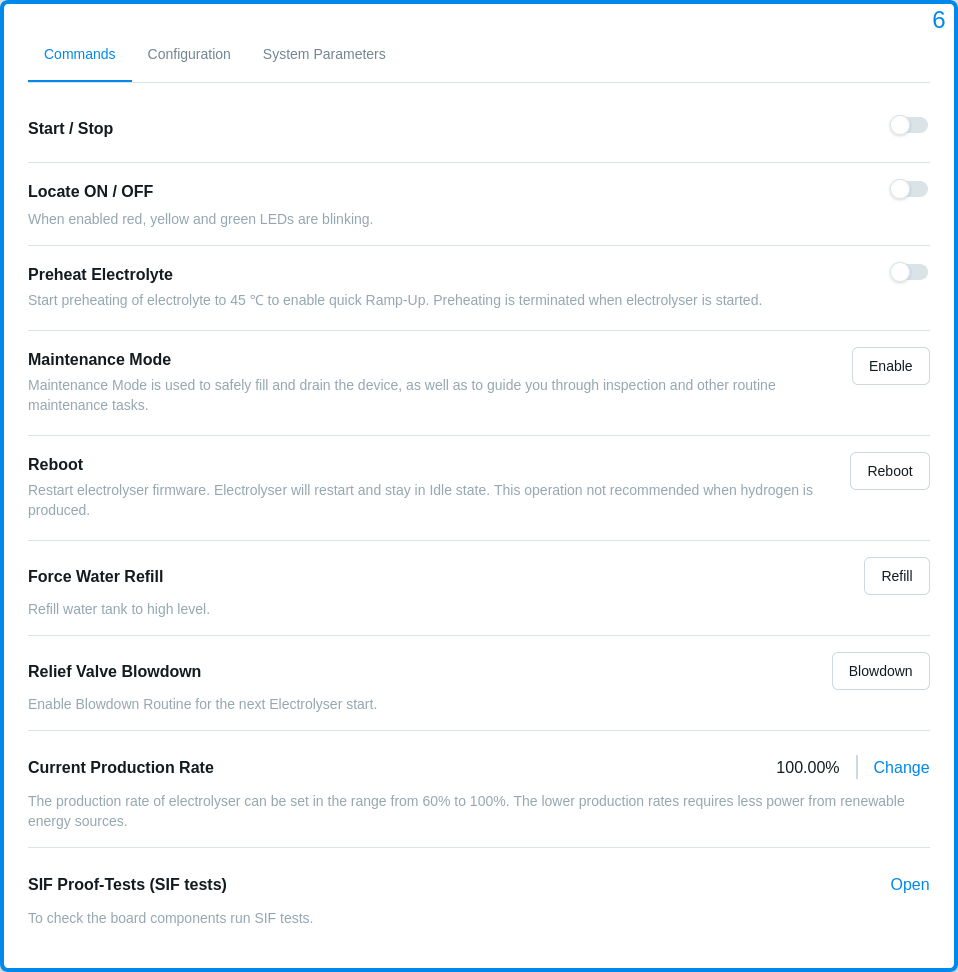
# Main Configuration Bar
Main Configuration Bar has 3 sub-layouts:
# Commands
# Start / Stop
Remote Start or Stop hydrogen production.
# Locate ON / OFF
Command to enable or disable the Locate device functionality.
When enabled red, yellow and green LEDs are blinking.
# Preheat Electrolyte
Command to start preheating of electrolyte to 45 ℃ to enable quick Ramp-Up. Preheating is terminated when Electrolyser is started.
Remote Start or Stop preheating of electrolyte.
# Maintenance Mode
Command to enable or disable Maintenance Mode.
Maintenance Mode is used to safely fill and drain the device, as well as to guide you through inspection and other routine maintenance tasks.
# Refilling
Refiling Electrolyser can be done by turning on the Maintenance Mode. The water tank must be empty or the electrolyte level must be less than Low Level.
When Maintenance Mode enabled and water level < Low Level you will switch to Electrolyte Refilling Wizard.
Follow steps in the Electrolyte Refilling Wizard to refill Electrolyser.
# Draining
Draining Electrolyser can be done by turning on the Maintenance Mode. The electrolyte level must be more than Low Level.
When Maintenance Mode enabled and water level > Low Level you will switch to Electrolyte Draining Wizard.
Follow steps in the Electrolyte Draining Wizard to drain Electrolyser.
After the Electrolyte Draining Wizard you will automatically switch to the Electrolyte Refilling Wizard.
# Reboot
Command to Reboot the device.
# Force Water Refill
Command to enable Force Water Refilling.
This command is used to refill the water tank to the High level.
# Cloud over Ethernet Beta EL 4 3.6.0
Warning
Cloud over Ethernet is in Beta.
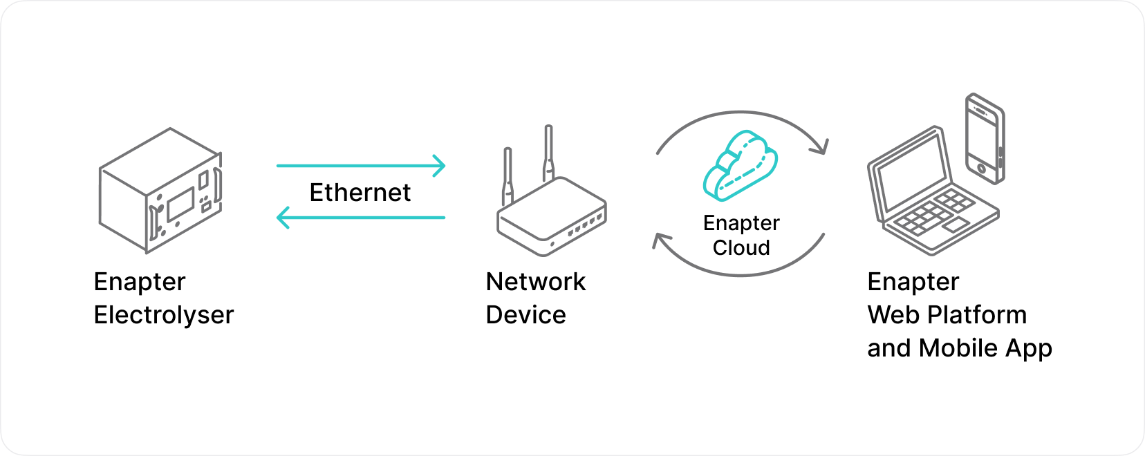
Cloud over Ethernet is a cutting-edge feature that empowers Enapter electrolyser users to seamlessly connect their devices to cloud services using an Ethernet interface. This advanced connectivity solution opens up a realm of possibilities for remote monitoring, data logging, and control of the electrolyser through a secure and efficient cloud platform.
The Enapter electrolyser is connected to a network with Ethernet capability, which provides a reliable and secure connection to the cloud platform. Through this connection, operational data, performance metrics, and status information of the electrolyser are transmitted to the Enapter Cloud for monitoring and analysis. Users can access the cloud platform from anywhere with an internet connection to view real-time data, adjust settings, and optimize the electrolyser's performance.
Cloud over Ethernet offers several advantages:
- Connection: Ethernet connections typically offer more stable and reliable connectivity compared to Wi-Fi, ensuring consistent data transmission and system control. For industrial applications Wi-Fi might not suitable due of the noisy radio environment or enterprise security policies while customers still want to benefit from 2-year warranty (opens new window).
- Remote Monitoring: Cloud over Ethernet enables users to remotely monitor the performance, status, and key metrics of the Enapter electrolyser in real-time. This capability provides unparalleled visibility into the operation of the electrolyser, allowing users to stay informed and proactive in managing their system.
- Data Logging: Operational data, performance metrics, and system logs are securely transmitted to the cloud platform for storage and analysis. By leveraging cloud-based data logging, users can access historical data, trends, and insights to optimize the performance and efficiency of the electrolyser.
- Control: With Cloud over Ethernet, users have the ability to remotely control and adjust various settings and parameters of the Enapter electrolyser through the cloud platform. This feature empowers users to fine-tune the operation of their electrolyser, respond to changing conditions, and optimize performance without the need for physical presence at the device.
By leveraging Cloud over Ethernet, users can enhance the efficiency, reliability, and convenience of managing the Enapter electrolyser, ultimately leading to improved performance and operational outcomes.
Note
When enabling or disabling Cloud over Ethernet on the electrolyser, please note that the process will initiate a reboot of the device. During this reboot, there will be a temporary loss of connection with the electrolyser. A Lost Connection message may appear for a few seconds until the device is back online and reestablished with the cloud platform.
Warning
Cloud over Ethernet will not work when Dryer Control Network (opens new window) is activated. And vice versa Dryer Control Network can not be activated when Cloud over Ethernet is enabled.
# Connection
Note
The DHCP mode must be configured and enabled on the router connected to Electrolyser.
This connection example showcases how the Cloud over Ethernet feature ensures a robust and efficient communication pathway, from the Enapter Electrolyser to the user interfaces, leveraging the reliability and speed of Ethernet connections.
# Enabling Cloud over Ethernet
Note
Delete the Dryer Control Network (opens new window) before enabling Cloud over Ethernet.
Note
Factory Settings Reset will set Cloud over Ethernet to Disabled.
- Temporarily connect your device to the Enapter Cloud via Wi-Fi using Enapter Mobile App (opens new window).
- To activate Cloud over Ethernet feature, contact Enapter Customer Support and provide the
UCM IDof the device. EnableCloud over Ethernet using Enapter Web GUI.
# DHCP and Static IP Settings 3.7.0
# DHCP
After Enabling Cloud over Ethernet you can choose DHCP connection without VLAN.
This documentation provides detailed steps for configuring the Electrolyser with DHCP:
- Enable Cloud over Ethernet.
- Select
DHCPas the network configuration type. - Press the
Applybutton to save the changes. Rebootthe Electrolyser.
By following these steps, you should successfully configure your Electrolyser to use DHCP without VLAN, ensuring it is operational with telemetry active and correctly displaying its new IP address on the Enapter Cloud page.
# Static IP
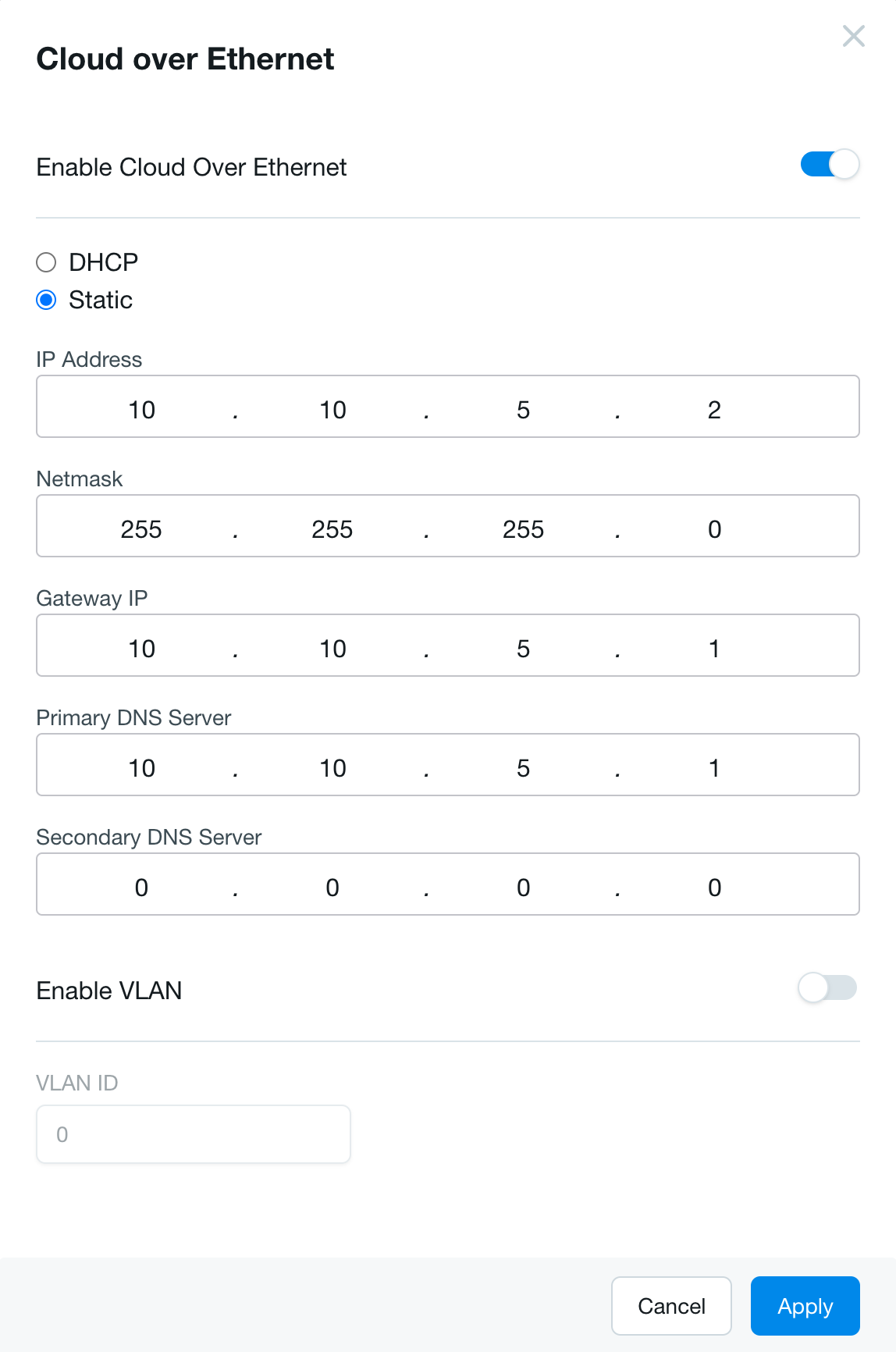
After Enabling Cloud over Ethernet you can choose Static IP connection without VLAN.
This documentation provides detailed steps for configuring the Electrolyser with Static IP:
- Enable Cloud over Ethernet.
- Select
Static IPas the network configuration type. - Enter the
IP Addressaddress assigned to the device. - Enter the
Netmaskcorresponding to the IP address. - Enter the
Gateway IPaddress. - Enter the
Primary DNS Serveraddress. Usually same as theGateway IPaddress. - Enter the
Secondary DNS Serveraddress. Not required, can be public (1.1.1.1 for example). - Press the
Applybutton to save the changes. Rebootthe Electrolyser.
By following these steps, you should successfully configure your Electrolyser to use a Static IP without VLAN, ensuring it is operational with telemetry active and correctly displaying its new IP address on the Enapter Cloud page.
# DHCP with VLAN
After Enabling Cloud over Ethernet you can choose DHCP connection with VLAN.
This documentation provides detailed steps for configuring the Electrolyser with DHCP with VLAN:
- Enable Cloud over Ethernet.
- Select
DHCPas the network configuration type. - Enable the
VLANoption. - Enter the
VLAN ID. This ID is crucial for the device to communicate on the correct VLAN. - Press the
Applybutton to save the changes. Rebootthe Electrolyser.
By following these steps, you should successfully configure your Electrolyser to use DHCP with a specific VLAN, ensuring it is operational with telemetry active and correctly displaying its new IP address on the Enapter Cloud page.
# Static IP with VLAN
After Enabling Cloud over Ethernet you can choose Static IP connection with VLAN.
This documentation provides detailed steps for configuring the Electrolyser with Static IP with VLAN:
- Enable Cloud over Ethernet.
- Select
Static IPas the network configuration type. - Enter the
IP Addressaddress assigned to the device. - Enter the
Netmaskcorresponding to the IP address. - Enter the
Gateway IPaddress. - Enter the
Primary DNS Serveraddress. Usually same as theGateway IPaddress. - Enter the
Secondary DNS Serveraddress. Not required, can be public (1.1.1.1 for example). - Enable the
VLANoption. - Enter the
VLAN ID. This ID is crucial for the device to communicate on the correct VLAN. - Press the
Applybutton to save the changes. Rebootthe Electrolyser.
By following these steps, you should successfully configure your Electrolyser to use a Static IP with a specific VLAN, ensuring it is operational with telemetry active and correctly displaying its new IP address on the Enapter Cloud page.
# Disabling Cloud over Ethernet
DisableCloud over Ethernet using Enapter Web GUI.
# Relief Valve Blowdown
Warning
Blowdown Routine for Electrolyser EL 4.0 and EL 4.1 is disabled due to Safety Board security restrictions.
Command to enable Blowdown Routine for the next Electrolyser start.
# Current Production Rate
Current hydrogen production rate. In percent.
To set Current Production Rate:
- Tap on the
Changebutton. - In the opened tab you can set the current production rate using range input or enter it using a keyboard.
- Tap on the
Applybutton to setCurrent Production Rate. - Tap on the
Cancelbutton to discard the changes. - Minimum production rate is limited to 60%. More information can be found in Enapter Knowledge Base (opens new window).
# SIF Proof-Tests EL 4
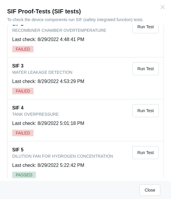
SIF Proof-Tests needed to check the board components.
Tap on the Run Test button to run the test.
For more information check EL 4.0 SIF Proof-Tests Documentation (opens new window) and EL 4.1 SIF Proof-Tests Documentation (opens new window).
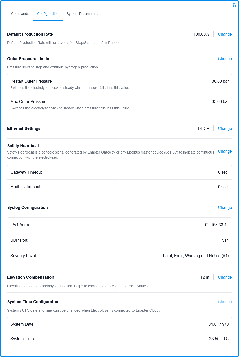
# Configuration
# Default Production Rate
Default hydrogen production rate. In percent.
Default Production Rate unlike Current Production Rate will be saved after Reboot.
To set Default Production Rate:
- Tap on the
Changebutton. - In the opened tab you can set the current production rate using range input or enter it using a keyboard.
- Tap on the
Applybutton to setDefault Production Rate. - Tap on the
Cancelbutton to discard the changes. - Minimum production rate is limited to 60%. More information can be found in Enapter Knowledge Base (opens new window).
# Outer Pressure Limits
Pressure limits to stop and continue hydrogen production.
To set Outer Pressure Limits:
- Tap on the
Changebutton. - In the opened tab you can change
Restart Outer PressureandMax Outer Pressure. Restart Outer Pressure- switches Electrolyser back to steady when pressure falls less this value. Must be <Max Outer Pressure.Max Outer Pressure- reaching this pressure switches Electrolyser to stand by and stops hydrogen production. Must be < 37.5 bar and >Restart Outer Pressure.- Tap on the
Applybutton to setOuter Pressure Limits. - Tap on the
Cancelbutton to discard the changes.
# Ethernet Settings
By default the DHCP is enabled.
If you want to change Ethernet settings please follow these steps:
- Tap on the
Changebutton. - In the opened tab you can change the following ethernet settings:
- IP Address
- Netmask
- Gateway IP
- Tap on the
Applybutton to changeEthernet settings. - Tap on the
Cancelbutton to discard the changes.
# Modbus TCP EL 4 3.6.0
Control Modbus TCP feature.
Enable Modbus TCP- Enable Modbus TCP to control Enapter Electrolyser via Modbus.Disable Modbus TCP- Disable Modbus TCP to free a TCP connection.
# Safety Heartbeat
Safety Heartbeat is a periodic signal generated by Enapter Gateway or any Modbus master device (i.e PLC) to indicate a continuous connection with Electrolyser.
To set Safety Heartbeat for Enapter Gateway or any Modbus master device:
- Tap on the
Changebutton. - In the opened tab you can set Safety Heartbeat timeouts. The value must be in seconds.
- Tap on the
Applybutton to set Safety Heartbeat timeouts. - Tap on the
Cancelbutton to discard the changes. - To disable
Safety Heartbeatfor Enapter Gateway or any Modbus master device timeouts must be set to0.
# Syslog Configuration
Note
Electrolyser EL 2.1 must be updated to firmware 1.8.0 or above.
Syslog Configuration can be enabled to receive system logs.
If you want to change Syslog Configuration please follow these steps:
- Tap on the
Changebutton. - In the opened tab you can change the following Syslog parameters:
- IPv4 Address - default
255.255.255.255 - UDP Port - default
514 - Severity - default
00- Disable1- Fatal Errors2- Fatal Errors and Errors3- Fatal Errors, Errors and Warnings4- Fatal Errors, Errors, Warnings and Notices5- Fatal Errors, Errors, Warnings, Notices and Debug Messages
- IPv4 Address - default
- Tap on the
Applybutton to changeSyslog Configuration. - Tap on the
Cancelbutton to discard the changes.
# Elevation Compensation
Note
Electrolyser EL 2.1 must be updated to firmware 1.9.0 or above.
Elevation setpoint of Electrolyser location. Helps to compensate pressure sensors values.
If you want to set elevation setpoint please follow these steps:
- Tap on the
Changebutton. - In the opened tab enter the setpoint in meters.
- Tap on the
Applybutton to change elevation setpoint. - Tap on the
Cancelbutton to discard the changes.
# System Time Configuration
Note
Electrolyser EL 2.1 must be updated to firmware 1.8.0 or above.
Warning
System Time Configuration disabled if Electrolyser connected to Enapter Cloud.
Set system's UTC date & time.
If you want to change System Time Configuration please follow these steps:
- Tap on the
Changebutton. - In the opened tab you can change the following parameters:
- System Date
- System Time
- Tap on the
Applybutton to changeSystem Time Configuration. - Tap on the
Cancelbutton to discard the changes. - Or you can synchronize System Date and System Time with your browser by clicking on the
Sync with your browser timebutton.
# System Parameters
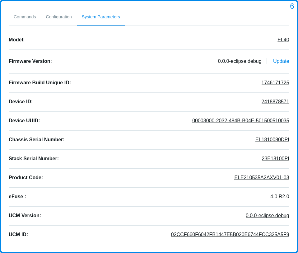
| Parameter | Description |
|---|---|
| Model | Model of Electrolyser. Must be EL21, EL40 or EL41. |
| Firmware Version | Current firmware version of Electrolyser (Ex: 1.6.0-r2.release).The Update button. Please check the Updating the Firmware Using Web GUI guide for more information. |
| Firmware Build Unique ID | Firmware build unique ID (Ex: 219560661). |
| Device ID | Device ID - unique, non zero integer value (Ex: 2418578571). |
| Device UUID | Device UUID - unique UUID (Ex: 00078000-2912-123B-B04E-999123543231). |
| Chassis Serial Number | Chassis serial number, configured on the factory (Ex: AA2101019SPI). |
| Stack Serial Number | Stack's serial number, configured on the factory (Ex: 23E21011PI). |
| Product Code | Product code, defined eFuses and configuration (Ex: ELE210535A2AXV01-03). |
| eFuse | Board's configuration stored in one time programming memory (Ex: 2.0 R1.0). |
| UCM Version | Current firmware version of the UCM (Ex: 1.8.0-rc.12.88300). |
| Ethernet MAC address | Ethernet MAC address unique ID (Ex: 00:80:E1:4F:92:76). |
| UCM ID | UCM ID - UCM's unique ID (Ex: 02CCF660F6042FB1447E5B020E6744FCC325A5F9). |
| Wi-Fi MAC address | Wi-Fi MAC address unique ID (Ex: C8:2B:96:A8:F5:2C). |
# Dryer Control Network
Note
Electrolyser EL 2.1 must be updated to firmware 1.8.0 or above.
Warning
To update Dryer's firmware using Electrolyser Web GUI Electrolyser EL 2.1 must be updated to firmware 1.9.0 or above.
Warning
To update Water Tank's firmware using Electrolyser Web GUI Electrolyser 2.1 must be updated to firmware 1.10.0 or above.
| Parameter | Description |
|---|---|
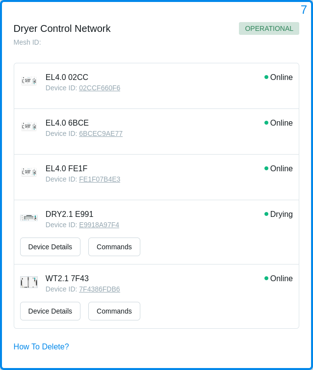
| Dryer Control Network | Status of the network.NOT CONNECTED - the network is not connected.CREATING - the network creating is in progress.INITIALIZING ERROR - the network creating failed.HEALTHY - the network is online.DEGRADED - the network has a warning.DOWN - the network is offline. |
| DCN ID | Mesh network unique ID. |
| Electrolyser | The list of Electrolysers (up to 5) connected to the Dryer Control Network. You can also check online/offline status of Electrolysers. |
| Electrolyser Device ID | UCM ID of Electrolyser. |
| Dryer | State of Dryer. The list of states 2.1 can be found on Dryer 2.1 page. The list of states can be found on Dryer 2.0 page. |
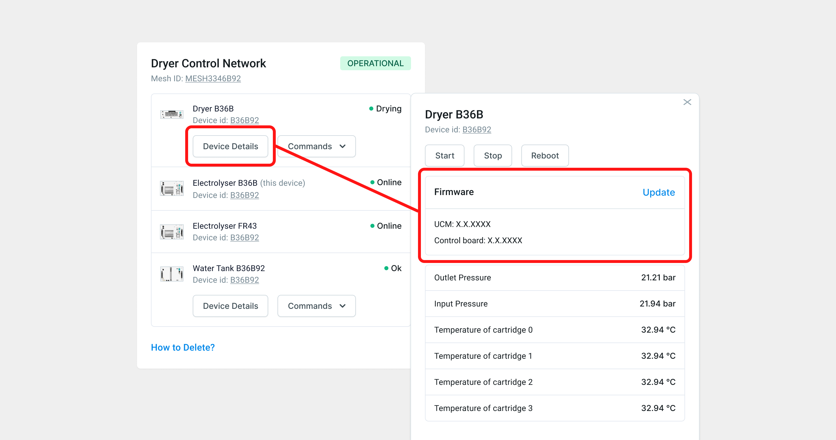
| Dryer Device Details | The list of all details of Dryer.Device ID - unique, non zero integer value (Ex: 1FBEFF813F).Commands to Dryer. List of events - Two first events of Dryer.Show all - The list of all events of Dryer.Firmware - Firmware version of Dryer and Dryer's UCM.Update - Wizard to update Dryer's firmware. lease check the Updating the Firmware Using Web GUI guide for more information.Input pressure - The pressure of the hydrogen on the input line of Dryer. In bar.Output pressure - The pressure of the hydrogen on the output line of Dryer. In bar.Temperature of cartridge 0 - Temperature of cartridge 0. In Celsius.Temperature of cartridge 1 - Temperature of cartridge 1. In Celsius.Temperature of cartridge 2 - Temperature of cartridge 2. In Celsius.Temperature of cartridge 3 - Temperature of cartridge 3. In Celsius. |
| Dryer Commands | Commands to Dryer. |
| Water Tank | State of Water Tank. The list of states can be found on Water Tank 2.1 page. |
| Water Tank Device Details | The list of all details of Water Tank.Device ID - unique, non zero integer value (Ex: 1FBEFF813F).Commands to Water Tank. List of events - Two first events of Water Tank.Show all - The list of all events of Water Tank.Firmware - Firmware version of Water Tank and Water Tank's UCM.Update - Wizard to update Water Tank's firmware. Please check the Updating the Firmware Using Web GUI guide for more information.Water level - Water level in Water Tank. In Liters.Inlet temperature - Temperature of inlet water. In Celsius.Tank temperature - Temperature of water in Water Tank. In Celsius.Conductivity - Conductivity of water in Water Tank. In μS/cm. |
| Water Tank Commands | Commands to Water Tank. |
| How To Delete? | Instructions how to delete the Dryer Control Network. |
# Updating the Firmware Using Web GUI
How to Get Firmware Package
If you are unable to update firmware using Enapter Cloud or Enapter Mobile Application, write to support@enapter.com and get files for offline update.
Never Upload Firmware Files Received From an Untrusted Source
Enapter is not responsible for any misbehavior or harm caused by untrusted firmware usage or violating update instructions.
It is always recommended to update the firmware using Enapter Cloud or Enapter Mobile Application. However these types of update require stable internet connection. In cases when it is not possible to have your device connected to Enapter Cloud it is possible to update the firmware using Web GUI.
# Updating Electrolyser
- Make sure you have physical access to the device before starting the update process.
- Remove Dryer Control Network (opens new window) before updating the firmware.
- If the Site has the Enapter Gateway, it needs to be updated to version 1.8.9 or higher.
- Save and unzip the received firmware package to local hard drive of your computer so that you have two files named
fw_ucm_0xXXXX_X.X.X.enaandfw_cbd_0xXXXX_X.X.X.enanext to each other. - Open Web GUI of your Electrolyser.
- Navigate to
System Parameterstab. - Click
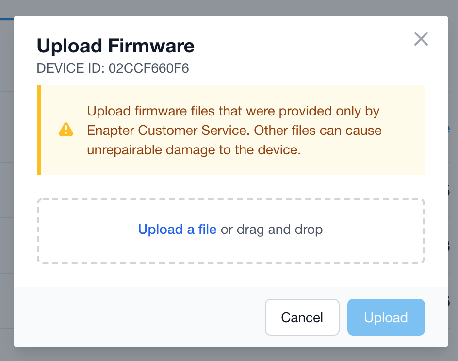
Updatelink. TheUpload Firmwarescreen will appear.
- Drag and drop or Select file with UCM firmware named
fw_ucm_0xXXXX_X.X.X.enafrom your local hard drive. - On the screen you will see the confirmation that the firmware file is recognized by showing the UCM Firmware version.
- Press
Uploadbutton and wait for the process to finish both theUploadandInstallationsteps. It will take up to 10 minutes. Don’t turn the Electrolyser off and don’t close the browser. - Press
Doneafter receiving the messageUCM firmware was updated successfully. - Drag and drop or Select file with Control Board firmware named
fw_cbd_0xXXXX_X.X.X.ena. - On the screen you will see the confirmation that the firmware file recognized by showing the Control Board Firmware version.
- Press
Uploadbutton and wait for the process to finish both theUploadandInstallationsteps. It will take up to 10 minutes. Don’t turn Electrolyser off and don’t close the browser. - Press
Doneafter you receive the messageControl Board was updated successfully.
# Updating Dryer or Water Tank Using DCN
Note
To update the firmware using Electrolyser Web GUI the Electrolyser must be updated to firmware 1.9.0 or above.
- Save and unzip the received firmware package to local hard drive of your computer the way you have two files named
fw_ucm_DRYER_X.X.X.enaandfw_cbd_DRYER_X.X.X.enanext to each other. For Water Tank files will be namedfw_ucm_WT21_X.X.X.enaandfw_cbd_WT21_X.X.X.ena. - Open Web GUI of your electrolyser.
- Navigate to
Dryer Control Networktab. - Navigate to
Device Details.
- Click
Updatelink. TheUpload Firmwarescreen will appear.
- Drag and drop or Select file with UCM firmware named
fw_ucm_DRYER_X.X.X.ena(fw_ucm_WT21_X.X.X.enafor Water Tank) from your local hard drive. - On the screen you will see the confirmation that firmware file is recognized by showing up the UCM Firmware version.
- Press
Uploadbutton and wait the process to finish withUploadandInstallationsteps. It will take up to 10 minutes. Don't turn the electrolyser and the dryer off and don't close the browser. - Press
Doneafter receiving the messageUCM firmware was updated successfully. - Drag and drop or Select file with Control Board firmware named
fw_cbd_DRYER_X.X.X.ena(fw_cbd_WT21_X.X.X.enafor Water Tank). - On the screen you will see the confirmation that firmware file recognized by showing up the Control Board Firmware version.
- Press
Uploadbutton and wait the process to finish withUploadandInstallationsteps. It will take up to 10 minutes. Don't turn the electrolyser and the dryer off and don't close the browser. - Press
Doneafter you will receive the messageControl Board was updated successfully. - To check the update was done successfully navigate to
Dryer Control Networktab in the Web GUI and checkDevice Details.
# 🧠 Quiz
Question 1/8
# 💬 Need Help?
Have a question or hit a roadblock? Join the Enapter Discord community (opens in a new tab) to get quick support, exchange ideas, and collaborate with other developers and energy experts.
Was this page useful?
